Loading...

Loading...
What is an intelligent lossless network?
Intelligent lossless network is an advanced technology that integrates flow control and congestion control, aiming to improve network performance and reduce latency. At the same time, it achieves the optimized integration of network and application systems through technologies such as intelligent lossless storage network. This technology provides a low packet loss, low latency, and high throughput network environment for application scenarios such as AI, centralized/distributed storage, and HPC, thereby accelerating computing and storage efficiency and creating a unified and integrated network infrastructure for data centers.
Why do we need an intelligent lossless network?
With the continuous evolution of data center technology, the limitations of traditional networks are becoming increasingly apparent. Emerging businesses such as high-performance computing, AI, and distributed storage have put forward higher requirements for data center networks. However, the traditional TCP/IP protocol stack has large resource consumption and high latency problems in key links such as data transmission and can no longer meet new requirements.
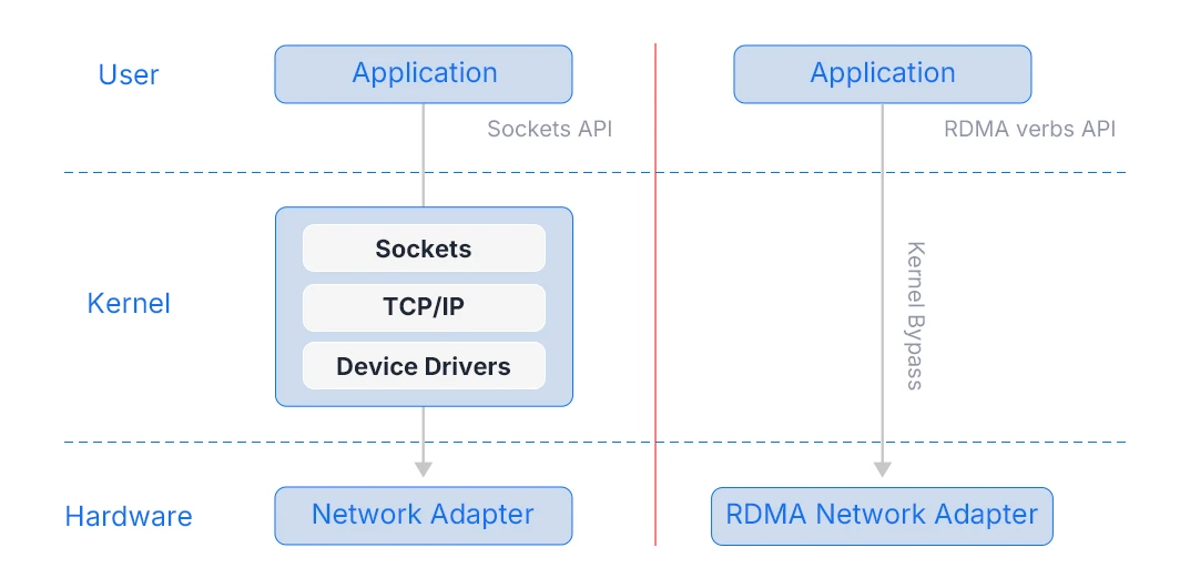
RDMA (Remote Direct Memory Access) is a high-speed network interconnection technology. The main design purpose of this technology is to reduce the processing delay and resource consumption of the sender and receiver during the data transmission process. RDMA technology enables computers to directly access the memory of remote computers and perform data transmission at the memory level without frequent CPU intervention, thereby significantly enhancing network communication performance.
Currently, distributed storage, HPC high-performance computing, AI artificial intelligence and other scenarios all use RoCEv2 (RDMA over Converged Ethernet version 2) as the transmission protocol on Ethernet to reduce transmission delay and CPU burden. Compared with traditional TCP/IP communication, RDMA not only reduces the resource occupation of the data transmission process, but reduces the data processing delay.
RDMA is a connectionless UDP protocol that lacks a complete packet loss protection mechanism and is extremely sensitive to network packet loss. At the same time, distributed high-performance applications are many-to-one communication Incast traffic models. For Ethernet devices, Incast traffic is prone to cause instantaneous burst congestion or even packet loss in the internal queue cache of the device, resulting in increased latency and decreased throughput, thereby damaging the performance of distributed applications. In order to bring out the true performance of RDMA and break through the network performance bottleneck of large-scale distributed systems in data centers, it is necessary to build a lossless network environment for RDMA with "no packet loss, low latency, and high throughput".
What key technologies do intelligent lossless network include?
Flow control technology
Flow control is a technology used to control the data transmission rate. Its main purpose is to prevent the sender from sending data at a rate that exceeds the processing capacity of the receiver. If the sender sends data too fast, the receiver's buffer may be full, resulting in data packet loss.
• PFC (Priority-based Flow Control): Provides priority-based flow control on a hop-by-hop basis to prevent packet loss caused by congestion and improve network reliability.
• PFC deadlock detection: Regularly detect the PFC deadlock status of the device to solve the problem of normal message forwarding.
Congestion control technology
Congestion control, as the core technology of intelligent lossless networks, is committed to avoiding or alleviating network congestion. When data traffic exceeds the processing capacity of the device, the network will face the risk of congestion, which will lead to data packet delay or loss.
ECN (Explicit Congestion Notification) is a congestion notification technology. It indicates the congestion status on the transmission path by marking the DS field in the IP packet header. Terminal devices that support the ECN function can use this mark to determine whether there is congestion on the path and adjust the sending method accordingly to prevent the congestion from worsening.
• ECN Overlay: Integrate ECN into the VXLAN network to realize ECN domain identification between the Underlay and Overlay networks, so that the congestion in the Overlay network can be perceived at the packet receiving end and the sending rate can be reduced.
• AI ECN: Use AI artificial intelligence technology to monitor network conditions and collect parameters in real time. Based on the current process feature judgment, calculate the optimal ECN threshold value to achieve accurate prediction and efficient control of network congestion.
Traffic Scheduling Technology
• Dynamic load balancing: By analyzing traffic, link status, and the load of each member link in real time, the best path is intelligently selected to achieve balanced traffic distribution and reduce the risk of delay and packet loss caused by overloaded links.
How to optimize parameters for intelligent lossless networks?
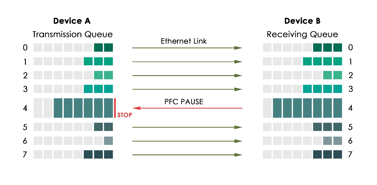
RoCE traffic needs to be guaranteed to run in a lossless queue. The lossless queue uses PFC technology, which can send Pause frames to a certain queue to force the upstream to stop the flow. When the device forwards the message, it enters the queue of the corresponding mapping relationship according to the priority of the message for scheduling and forwarding. When the sending rate of a certain priority message exceeds the receiving rate, resulting in insufficient available data buffer space on the receiving end, the device feeds back to the previous hop device through the PFC PAUSE frame. After receiving the PAUSE frame message, the previous hop device stops sending messages of this priority until it receives the PFC XON frame or after a certain aging time, it can resume traffic sending. This article explains the specific PFC configuration restrictions and setting guidelines.
Switching chips have fixed pipelines, and buffer management is in the middle of the in-chip process and the out-chip process. When the message is in this position, the ingress and egress information of the message is already known, so logically it can be divided into the ingress direction and egress direction to manage the cache separately.
The PFC waterline is triggered based on the ingress buffer management. The chip provides 8 queues in the ingress direction. We can map service packets of different priorities to different queues, thereby providing different buffer allocation schemes for packets of different priorities.
For each queue, its buffer allocation is designed into three parts according to the usage scenario: guaranteed cache, shared cache, and headroom.
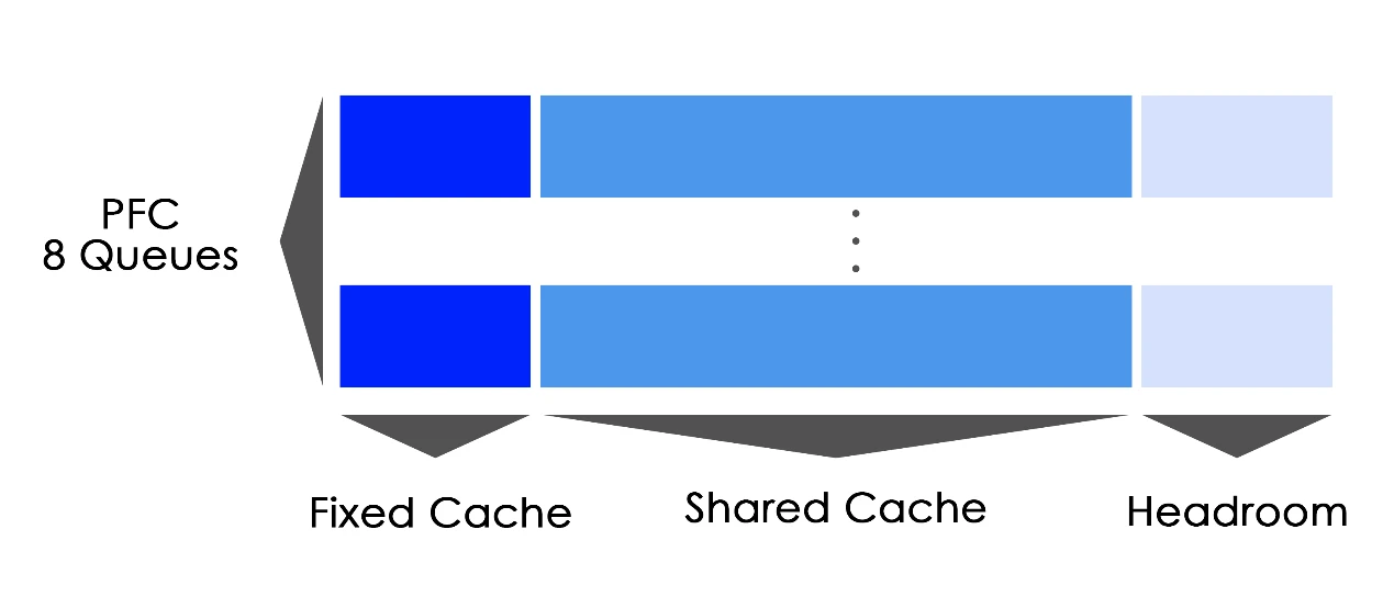
• Guaranteed cache: A dedicated cache for each queue, ensuring that each queue has a certain amount of cache to ensure basic forwarding;
• Shared cache: A cache that can be applied for use when traffic bursts, shared by all queues;
• Headroom: A cache that can continue to be used after the PFC waterline is triggered until the server response slows down.
PFC threshold setting type
By configuring the PFC buffer threshold, you can effectively solve problems such as tail discard of the sending data buffer due to insufficient buffer space and too large a number of inbound traffic queues.
PFC currently provides the following threshold setting types:
• Headroom cache threshold: The maximum cell resource usage of a certain 802.1p priority message in the headroom storage space. When the used cell resources are reached, the interface will discard the received message.
• Back pressure frame trigger threshold: The upper limit of the cell resource usage of a certain 802.1p priority message in the shared storage space. When the upper limit is reached, the PFC function will be triggered to send a PAUSE frame.
• Dynamic back pressure frame trigger threshold: Set the percentage of available cell resources for a certain 802.1p priority message to trigger a PFC PAUSE frame.
• Static back pressure frame trigger threshold: Set the available cell resource threshold for a certain 802.1p priority message to trigger a PFC PAUSE frame to a fixed value.
• Offset between the back pressure frame stop threshold and the trigger threshold: When the cell resources used by a certain 802.1p priority message decrease by a fixed value, stop sending PFC PAUSE frames to allow the peer device to resume traffic transmission - the offset of sending Xon after the Xoff watermark drops.
• PFC reservation threshold: The cell resources reserved for a certain 802.1p priority message in the guaranteed storage space. The guaranteed cache is a static watermark (fixed and exclusive).
• Headroom maximum available cell resources: Configure the size of the cell resources of a certain cache pool in the headroom storage space.
In AI training scenarios, PFC provides lossless transmission guarantees for RoCEv2/RDMA through buffer watermarks and queue scheduling, while ECN enables fast end-to-end congestion detection and mitigation, working in conjunction with intelligent scheduling to optimize link load. This approach fully unleashes the performance advantages of RDMA—low latency and low CPU overhead—while avoiding issues such as congestion and deadlock, thereby delivering low-latency, high-throughput, stable, and reliable network support for large-scale AI clusters.